
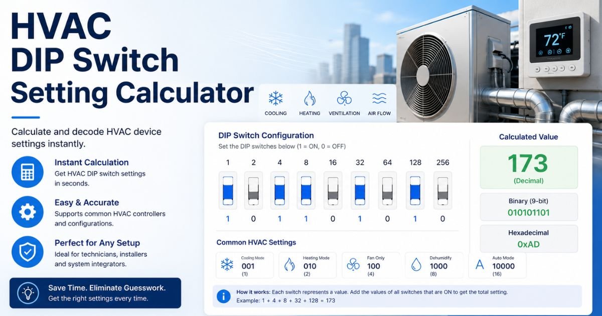
HVAC DIP Switch Setting Calculator
Configure your system’s control board profile seamlessly. Switch between system tonnage requirements or build custom profiles using live switch toggles.
Frequently Asked Questions
Manufacturers use physical DIP switches so a single control board can be installed across multiple equipment sizes. It allows technicians to tell the board precisely what tonnage blower motor or heating system configuration is attached.
Incorrect configurations can cause weak airflow, system coil freezing (evaporator ice-ups), loud register noise, short cycling, or complete system component lockout codes.
The standard rule of thumb for standard residential air conditioning and heat pump systems is roughly 400 CFM (Cubic Feet per Minute) of airflow per ton of cooling capacity.
Blower Off Delay options keep the indoor fan running for a designated time (e.g., 30 to 90 seconds) after the compressor shuts off to extract residual cooling or heating trapped inside the ductwork.
Yes. Always disconnect the main electrical breaker and 24V transformer power. Most HVAC microprocessors only scan DIP switch layouts upon boot-up; mid-operation adjustments will not register and risk shorting components.
Nominal provides standard default airflow speeds. Many circuit boards include secondary “Adjust” switches that raise or lower that baseline CFM by 10% to account for high-static duct restrictions or humid climates.
Control boards group switch blocks into channels (e.g., Cool, Heat, Delay). Look for schematic labels silk-screened directly onto the green circuit board or consult the wiring diagram glued to the blower door.
Variable-speed ECM blower motors use specific DIP switch selections to dictate soft-start profiles, ramping up slowly over several minutes to optimize humidity extraction and reduce acoustic startup noise.
Yes. If switches are set to an airflow value too low for a large compressor (e.g., 1.5-ton airflow setting paired with a 4-ton compressor), liquid refrigerant can flood back to the compressor crankcase, damaging internal valves.
No. Layouts are proprietary. While one brand uses binary logic where switches 1 and 2 select tonnage, another may use them for electric auxiliary heat strip delays. Always reference your exact model manual.
Configuring HVAC Control Board DIP Switches: A Field Technician’s Optimization Guide
Modern furnaces, air handlers, and modular fan coils use increasingly sophisticated microchips to run high-efficiency blowers. Despite this advanced technology, the physical setup interface relied upon by major brands remains mechanical: the trusty DIP (Dual In-line Package) switch block.
Improperly configured DIP switches during commissioning account for a massive percentage of post-installation callbacks. Whether you are addressing an improper air-conditioner fan speed profile or setting up a staging delay for a multi-stage heat pump, utilizing our HVAC DIP Switch Setting Calculator bridges the gap between complicated instruction manuals and flawless field work.
The Crucial Link Between DIP Switches and CFM
The primary role of the switch array on an indoor air handler or furnace mainboard is managing CFM (Cubic Feet per Minute) delivery. Airflow dynamics require exact volume settings to protect the compressor and transfer thermal energy effectively:
- Too Little Airflow: Evaporator coils quickly drop below freezing ($32^\circ\text{F}$ / $0^\circ\text{C}$), causing condensation to lock up into solid ice and cutting off cooling completely.
- Too Much Airflow: Air passes across the cooling coil too quickly for proper moisture removal, leaving indoor spaces feeling cold but uncomfortably humid.
By mapping out standard systems at approximately 400 CFM per ton of nominal cooling, matching your switch block selection ensures your multi-speed or variable ECM motor maintains optimal static balance.
How to Map HVAC Control Switches manually
While proprietary layouts exist, most multi-tonnage residential equipment scales across a common 4-position binary matrix pattern. For instance, a common manufacturer template maps out fan settings using combinations of Switch 1 and Switch 2:
| Switch 1 | Switch 2 | Configured Mode / Equivalent Tonnage |
|---|---|---|
| OFF | OFF | 1.5 Tons (Low Speed Setup) |
| ON | OFF | 2.0 Tons (Medium-Low Speed Setup) |
| OFF | ON | 2.5 Tons (Medium-High Speed Setup) |
| ON | ON | 3.0 Tons (High Speed Setup) |
Golden Rules for Safe Programming on the Job Site
1. Kill Power First: Never flip switches while the system is live. Low-voltage shorts can instantly fry sensitive microprocessors, and many control modules ignore adjustments completely unless power is re-applied from a clean cold-boot.
2. Inspect the Static Pressure: High static pressure (restrictive, narrow duct networks or clogged air filters) shifts motor performance profiles. If your manual calculation calls for 1200 CFM but the ducts are restrictive, you may need to leverage secondary “Trim/Adjust” switches to bump fan settings up by 10%.
3. Document Changes: When overriding default factory specs, use a permanent marker on the internal blower housing panel to write down the modified layout. This saves valuable diagnosis time for the next maintenance technician.